Oct. 22, 2026
Choosing the thickness of a capacitive touchscreen is not merely about selecting a "standard figure"; rather, it is a balancing act between signal
penetration, mechanical protection requirements, and structural feasibility. Thickness directly determines the degree of attenuation in the
capacitive coupling between a finger and the sensor. An incorrect choice can lead to sluggish touch response, edge distortion, or insufficient
strength in the cover lens.
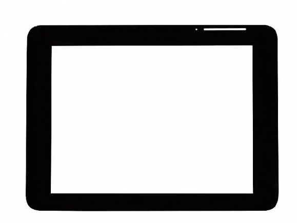
Fundamentally, thickness is an electrical consideration. The cover lens sits between the finger and the sensor electrodes; as thickness increases,
the path the finger’s electric field must travel to reach the electrodes lengthens, causing a reduction in the change in capacitance (ΔC) triggered
by a touch. Empirical data shows that for every 1 mm increase in cover lens thickness, the change in capacitance drops by approximately 35%.
The signal-to-noise ratio (SNR) falls from >40 dB for thin cover lenses (≤0.7 mm) to 25–35 dB for standard ones (0.8–1.8 mm), and drops below
20 dB for thick cover lenses (≥2.0 mm). When the SNR falls below ~20 dB, it becomes significantly more difficult for the controller to distinguish
a genuine touch from background noise, resulting in increased positioning errors, failure of edge-touch detection, or the need for firmer pressure.
Microchip’s sensor design guidelines also impose constraints: a cover glass thinner than 0.5 mm is susceptible to interference from moisture,
while one exceeding 2.5 mm results in an unacceptably low SNR. This defines the "electrical comfort zone" for conventional mutual-capacitive
touchscreens—typically a glass cover lens between 0.5 mm and 2.5 mm thick. Anything outside this range requires specialized compensation
at the controller or sensor-pattern design level.
Within this range, the specific application dictates the design priority. Consumer electronics push for minimal thickness; smartphones and tablets
typically utilize cover lenses of 0.55 mm, 0.7 mm, or 1.1 mm, while portable medical devices and handheld industrial terminals often fall within the
0.55–0.7 mm range to achieve a lightweight, slim profile and high sensitivity. The trade-off is a reduced margin for impact resistance, making drop
protection heavily reliant on the inherent properties of the chemically strengthened glass itself. In industrial and medical applications, protection
and chemical resistance are the primary considerations. Cover glass thickness in these sectors can range from 0.7 mm to 8 mm; for industrial
control systems, 1.8–3.0 mm is standard, while explosion-proof devices may even require reinforced glass exceeding 3.0 mm—a requirement
managed by using signal-gain algorithms to compensate for attenuation. Automotive center consoles occupy a middle ground, where 1.1 mm
is widely regarded as the optimal balance between impact resistance, optical quality, and touch sensitivity. Curved automotive cover glass is
also typically kept at ≤1.1 mm, allowing the glass to flex and conform to the required curvature.
Another often-overlooked factor in thickness selection is that the display structure itself consumes part of the total thickness budget. In a GG
(glass-on-glass) configuration, the two stacked layers of glass result in a thicker module—typically around 1.4 mm. OGS (one-glass solution)
integrates the sensor into the cover glass, reducing the thickness by approximately 0.4 mm compared to GG. In-Cell technology goes further
by eliminating the physical gap between the external touch layer and the display panel, offering a thickness reduction of up to 0.44 mm—a
decrease of roughly 25%. This means that for products with strict total-thickness constraints, it is not always necessary to sacrifice cover glass
thickness; adopting a more highly integrated structure can free up space while maintaining sufficient glass strength.
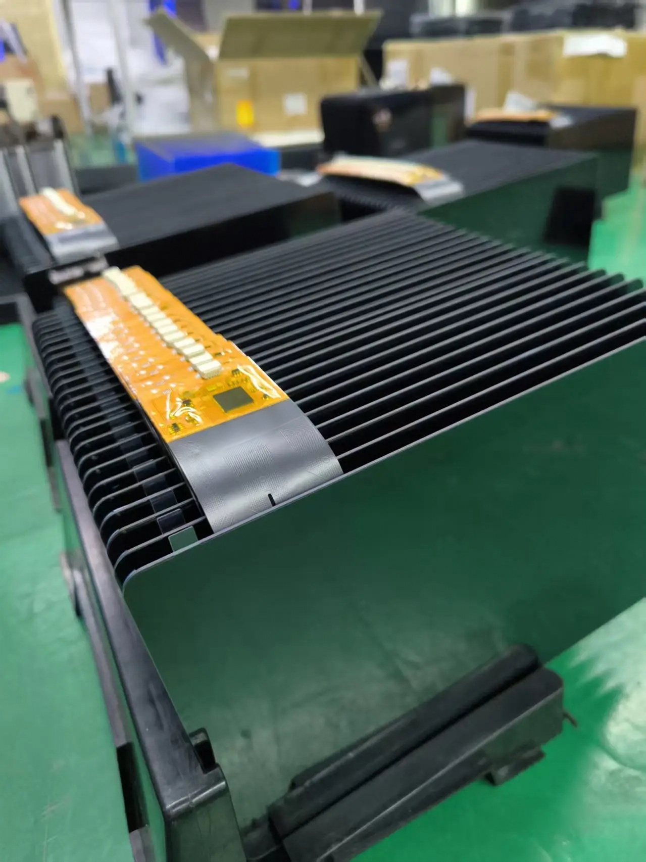
Therefore, the selection process should follow this logic: first, determine the minimum cover glass thickness required by the operating environment;
then, verify whether the resulting signal attenuation falls within the compensation capabilities of the chosen controller and sensor pattern. If it does
not, the priority should be to reduce the thickness of the display structure or upgrade the sensor/controller, rather than simply thinning the cover glass.
There is no inherent "better" or "worse" thickness value; the "correct" thickness is simply the one that allows for reliable signal transmission.
Previous None
+0086 755 21042870
+0086 755 2822 5493
Shenzhen Company: 5/F, Building 211, Tairan Science Park, Tairan 4th Road, Shatou Street, Futian District, Shenzhen(518040), China.
Dongguan Factory: 2/F, Building D, Fulin Industrial Park, Weixi Road, Dalingshan Town, Dongguan City(523831), Guangdong,China
NAVIGATION
REQUEST A QUOTE



Scan to wechat